
Timeline: Jan-May 2025
Objective
This project was done as part of MIT Wind, a competitor in the US Department of Energy's 2025 Collegiate Wind Competition. The competition had four main components that contributed to your team's overall score: turbine design, turbine testing, connection creation, and project development. MIT Wind had primarily two teams: build and project development. The build team worked on the turbine design and testing, and the project development team focused on (of course) project development as well as connection creation.
Outcomes & Contributions
As a member of the mechanical subteam of MIT Wind, I largely worked on the foundation.
- We opted for 6" inner-diameter PVC pipe as the main foundation material to fit our spar-buoy design.
- Pre-competition, for stability, we used 6" diameter foam in the upper portion for buoyancy; we left the middle portion flooded; and for the ballast, we used 6" diameter steel discs placed as low as possible to ensure that our center of gravity was as below the center of buoyancy as possible for optimal stability.
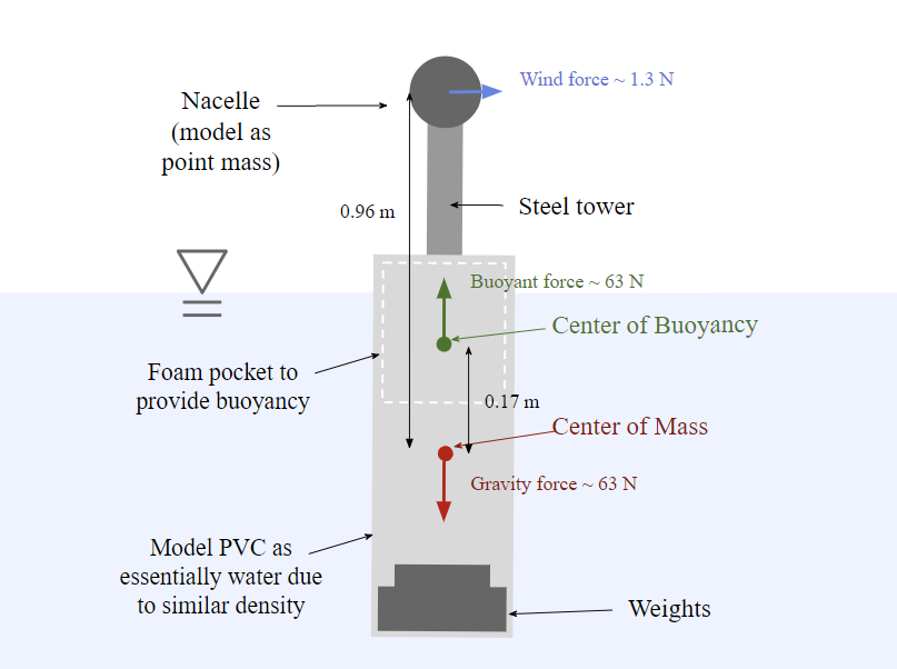
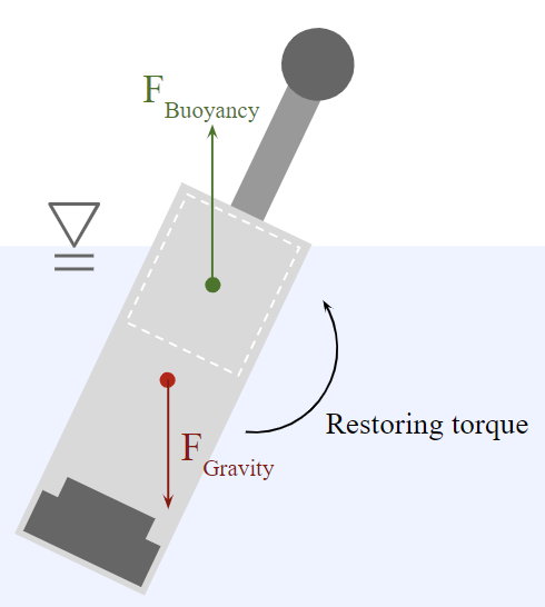
Figure 1: free-body diagrams of the turbine -
We created a model for the oscillatory behavior of the foundation.
The equation of motion we derived for the turbine was:
$$\ddot \theta + \frac{\rho C_d D L^4}{8 I_{sys}} \dot \theta |\dot \theta| + \frac{F_b L sin(\theta)}{I_{sys}} = 0 \text{,}$$
where $I_{sys}$ is the moment of inertia of the system, $D$ is the diameter of the PVC tube, $L$ is the length of the submerged portion of the buoy, $F_b$ is the buoyancy force, $\rho$ is the density of water, and $C_d$ is the coefficient of drag, approximated from the cylindrical geometry of the submerged PVC tube. $I_{sys}$ is 0.9625 kg-m2. $C_d$ was estimated to be 1.1.
Since this equation can't be solved analytically, we used MATLAB's ode45 to solve it numerically. The graph is pictured below.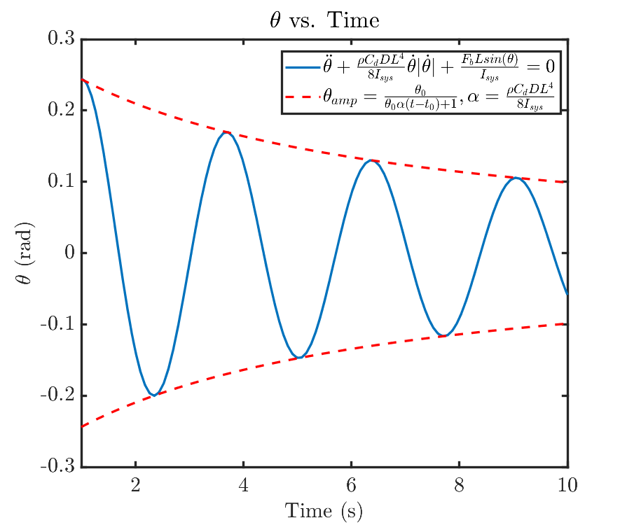
Figure 2: model of the oscillatory behavior of the foundation. From this, we knew that the turbine would be more stable with more damping. - We developed an idea for fins inspired by SpaceX fins to increase damping; grid-style fins were used to prioritize viscous drag, which is more predictable than form drag.
- We designed what we called the "puck," which connects the base flange of the steel tube tower to the top of the PVC.
- I designed an attachment to connect a linear actuator to the pitch control of the blades, made using laser cut acrylic pieces and a linear ball bearing. The linear ball bearing was used to reduce the linear friction that would lead to the pitch control getting stuck, but it ended up being a mistake, as it greatly increased the rotational friction of the turbine, leading to the overall attachment's removal in the final test at the official competition.
-
Below is the overall turbine right before arriving at the competition.
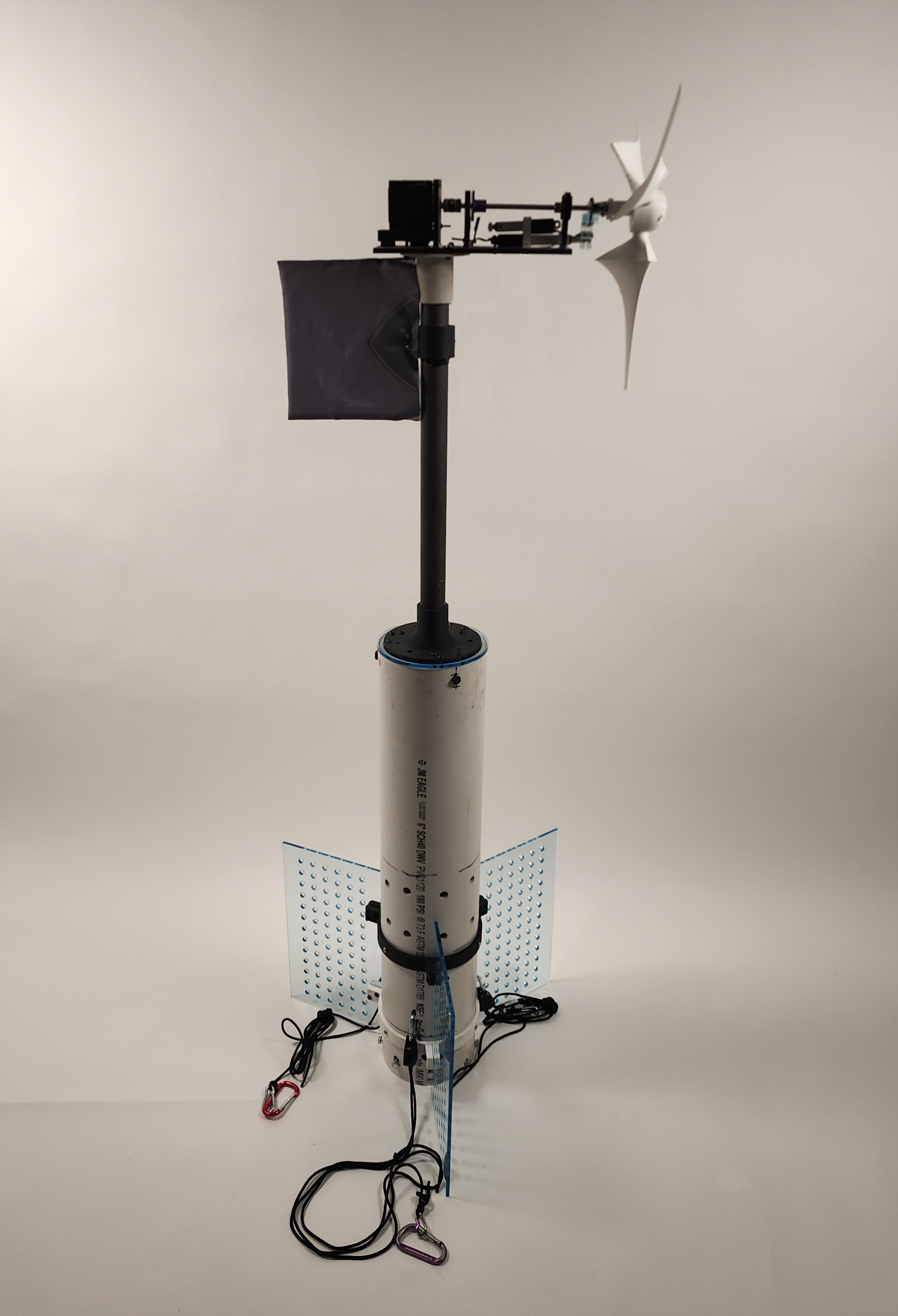
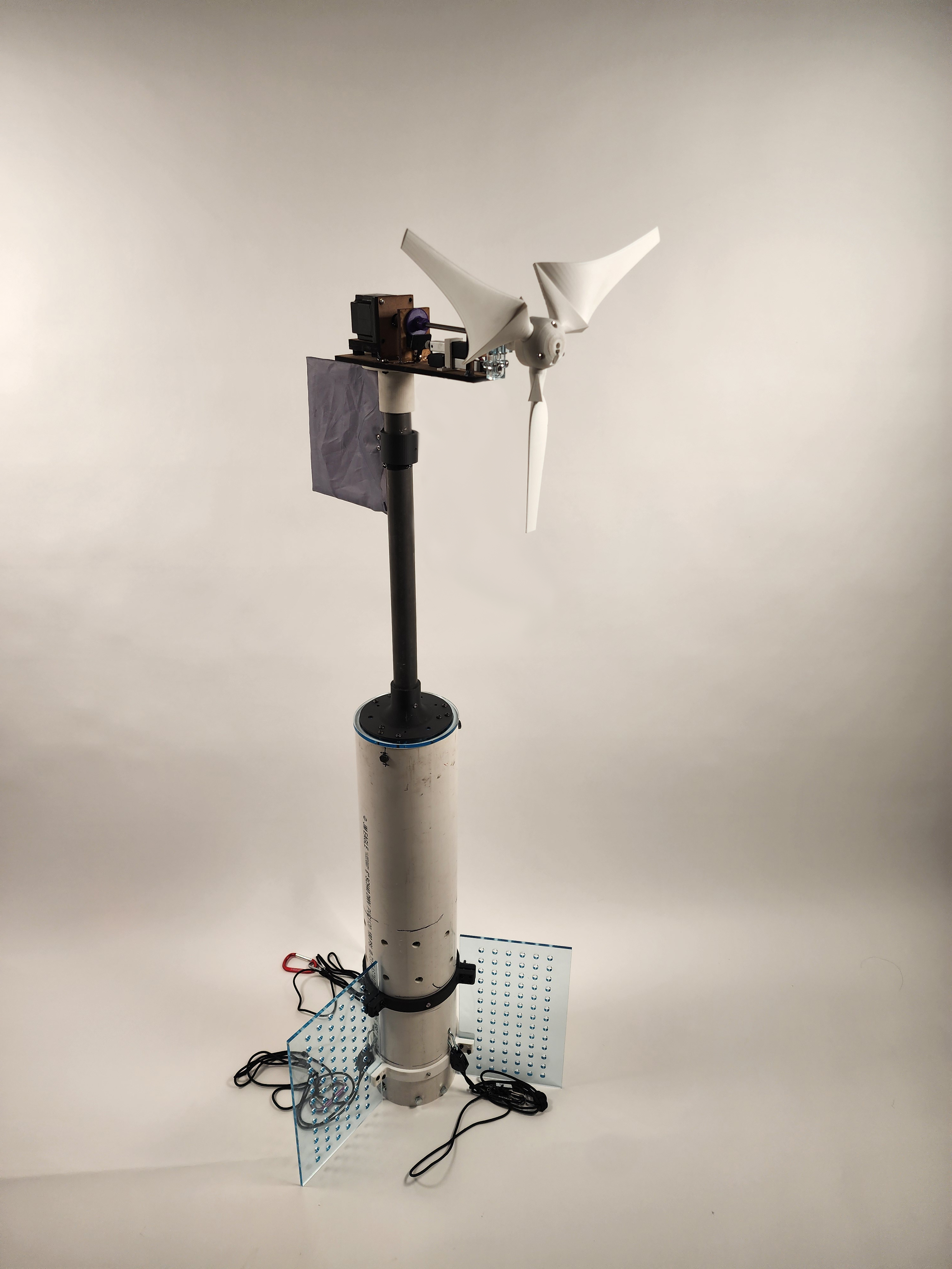
Figure 3: entire turbine assembly -
At the competition, we found that there still was not enough buoyancy and that the center of buoyancy was also not high enough, so we bought pool noodles and wrapped them around the top of the foundation. This significantly increased the stability of the turbine. Also, we added a set of mooring lines near the top of the foundation to prevent tipping. This was very effective, as our turbine managed to not tip past 15° after our final test, enabling us to pass all foundation-related scoring at the competition.
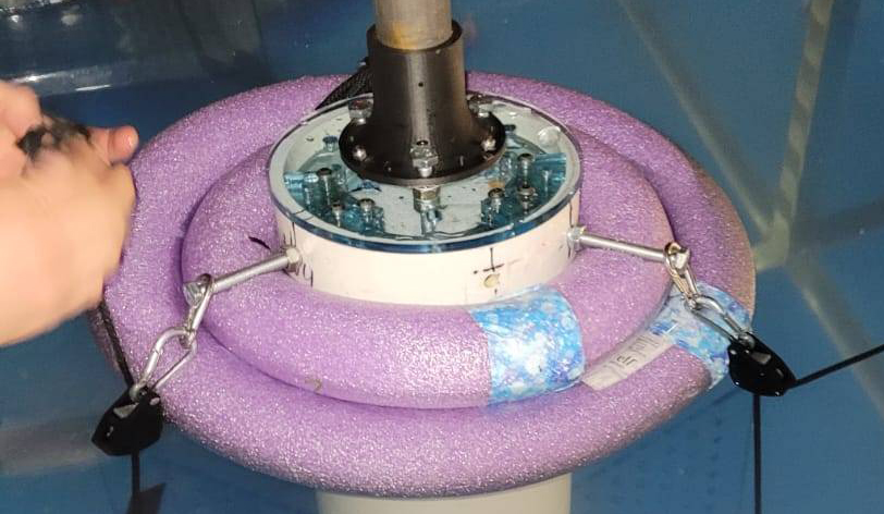
Figure 4: foundation now with pool noodles and additional set of mooring lines
Technical Details & Skills
Manufacturing: Lathe, Drill Press, Bandsaw, Handsaw/Hacksaw, 3D printing, soldering
Languages: MATLAB, C++ (for Arduino)
CAD: Fusion360, Onshape
