
Date: 10/05/2025
TABLE OF CONTENTS
Oh no
Hi! If you read my previous blog post, you would have seen me proudly announce my interest in building a custom generator. Current me loathes past me for letting my hubris utter these words. If I am being honest, I am a bit in over my head. However, I should at least try since my future career (hopefully smth in sustainable energy, trains, cool stuff, etc.) depends on me having somewhat of a grasp on magnetics.
Basic science
The reason why I thought building a generator wouldn't be so bad is because in principle, it is quite uncomplicated.
The purpose of a generator is to convert mechanical power to electrical power (opposite of a motor). To do this, you rely on Faraday's law: $$ \varepsilon = -N \frac{d\Phi}{dt} \text{,}$$ where $\varepsilon$ is the induced electromotive force (EMF) or induced voltage, $N$ is the number of turns in the circuit, and $\frac{d\Phi}{dt}$ is the change in magnetic flux over time.
This equation describes how a change in magnetic flux will induce voltage in a circuit. The negative sign arises from the fact that a circuit will resist change in a magnetic field, known as Lenz's law, so an increasing magnetic flux will induce a current with an opposing magnetic field, and vice versa. I like to reconcile this with the idea that systems generally resist change; we see this a lot in mechanical systems, where objects resist changes in velocity.
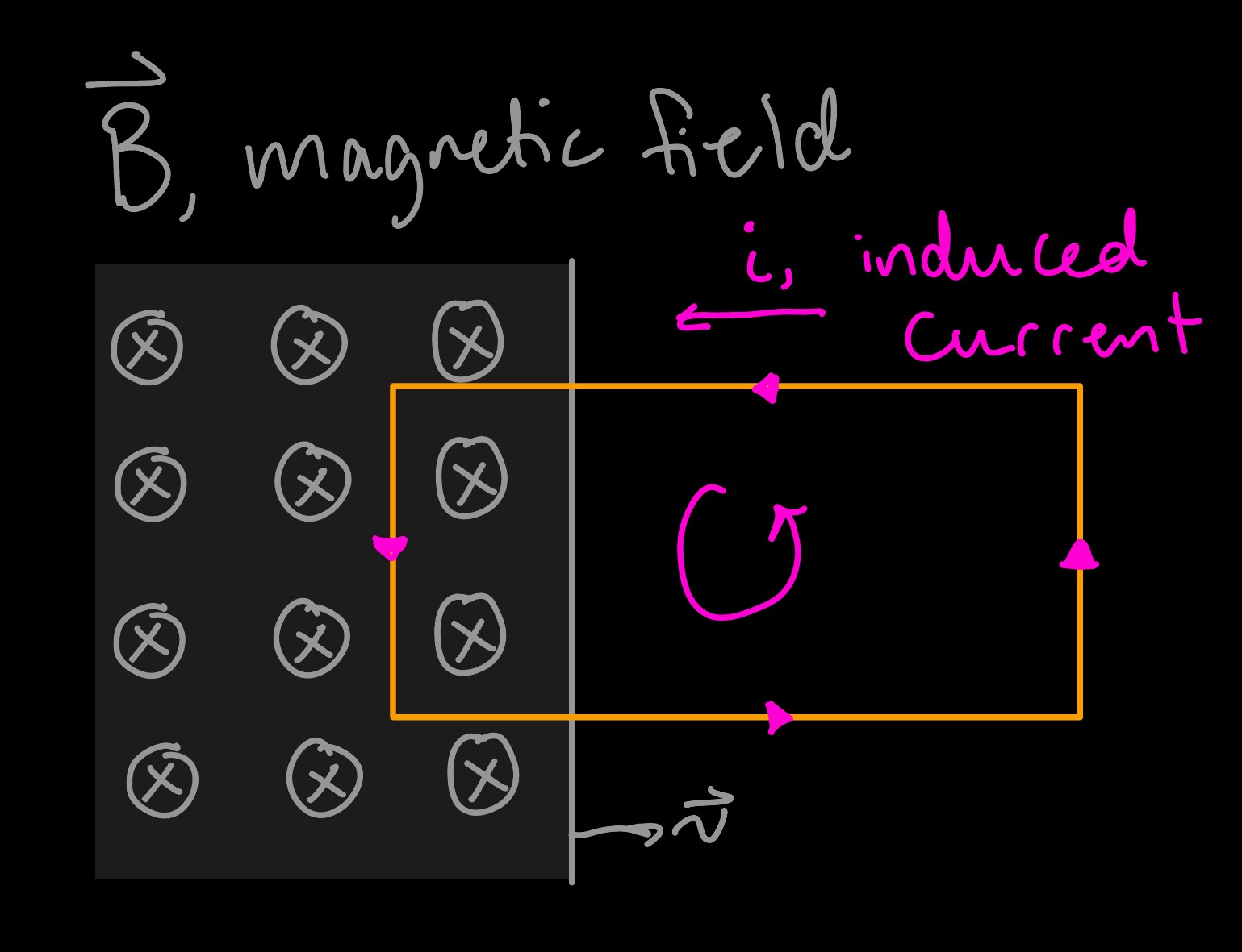
As the magnetic field moves right, the magnetic flux in the circuit will increase, leading to an induced current with an opposing magnetic field.
Faraday's law dictates the design for the two main components of a generator: the stator and rotor. The stator is the stationary component of a generator equipped with a bunch of wire coils. You want to pack in as many turns as possible since according to Faraday's law, more turns lead to more voltage. The spinning part of a generator is called the rotor. It is equipped with magnets with a magnetic field perpendicular to the coils, and you alternate the magnets with opposite polarities to change the magnetic flux as you spin the rotor.
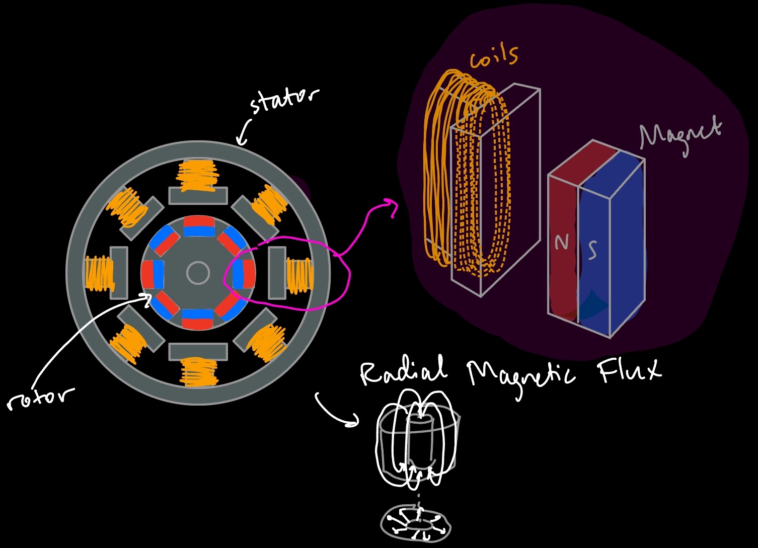
Top view of generator showcasing the stator and rotor. This generator specifically is a radial flux generator, but there are different types, such as the axial flux generator.
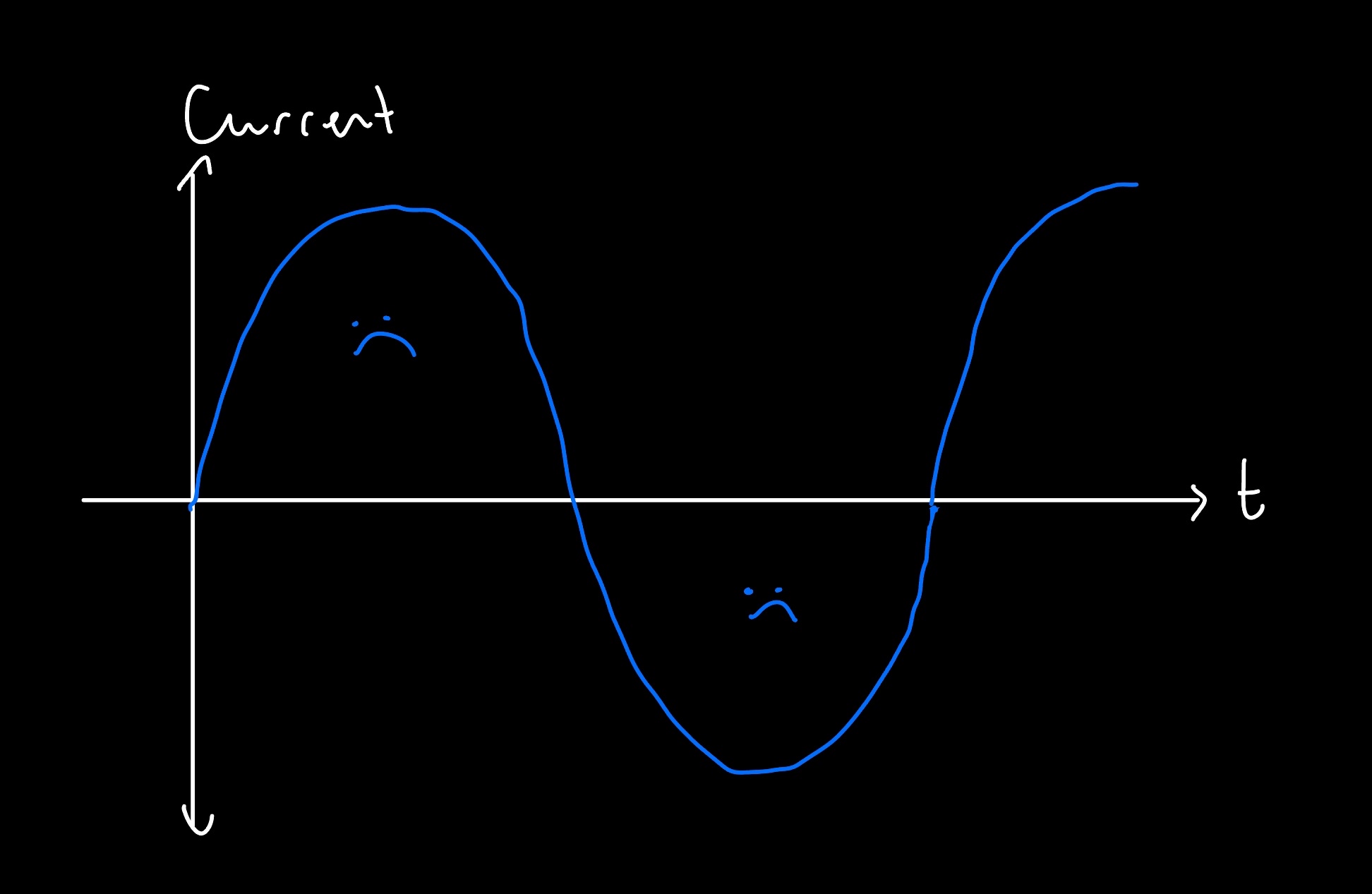
From what I've seen, the exact ratio of number of magnets to coils depends on your design, which can be 1:1*, 2:1, 4:3, etc. (*generally, you don't want a 1:1 ratio though, so sorry that my drawing didn't take this into account). This source says that a ratio of 12 magnets to 9 coils produces a clean three-phase output, so I'll be going with this. Why three-phase? It's to keep the system more power efficient. This is because the induced voltage coming from a generator will always be alternating current (AC) since the magnetic flux will be rapidly changing from one direction to the other, and from the graph below, a one-phase generator's induced current will end up looking like a sine wave.
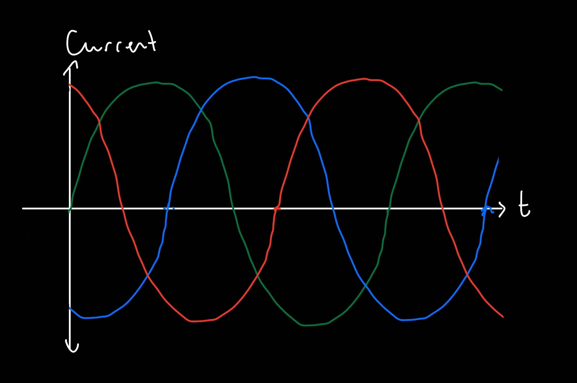
A three-phase generator minimizes power losses by maintaining a more consistent amount of current/voltage, as pictured below, with no periods of zero current. You accomplish this by having the number of coils be an integer multiple of three, which allows you to stagger three sets of voltage by 120°.
Even after all of this, YOU ARE NOT DONE! You will need a full-wave (bridge) rectifier to convert AC to DC. It is necessary so that the current/voltage stays unidirectional, which is what we can actually use for energy. I'm lazy, so I will not be drawing this out, but here is a good resource on understanding how a basic rectifier works. You should throw in a capacitor to smoothen the voltage across the load.
There are some other things to keep in mind. For radial flux generators, you want the coils wrapped around iron cores to help minimize the air gap (open space between stator and rotor), as bigger air gaps reduce efficiency. Iron cores also help with concentrating the magnetic flux. Additionally, steel is a good material for the stator and rotor since it helps increase magnetic permeability. However, this comes at a cost: eddy currents. To minimize eddy currents and therefore overheating and power losses, good generators have stators and rotors made from a bunch of stacked laminated electrical steel sheets, which are insulated from each other and are oriented to minimize the surface area available to eddy currents. My understanding is that these things aren't cheap, and you need hundreds of layers, so I am unsure if I will actually be able to get my hands on these. However, they're often thin enough that you can just laser cut them, so we'll see.
Designing our own generator
Now onto finally designing our own generator!
For some constraints, I used the 2024-2025 CWC Rulebook for suggested specifications.
The max allowed voltage for the load is 48 volts, and the turbine+rotor system must fit within a 45x45x45 cm cube. Using this, we know that the max acceptable swept area (area that turbine blades "sweep") is going to be 0.45 m in diameter or 0.159 m2.
I found this absolute gold mine of a resource on where to continue. We:
- use the equation for kinetic energy, $\frac{1}{2} m v^2$
- rewrite the mass of air to be $\rho_a \Delta t v A $ ($ \rho_a $ is the density of air, ~1.225 kg/m3, $ \Delta t v $ is an arbitrary distance, and $A$ is the swept area we're considering)
- plug in this new mass and take the time derivative (rewrite to where we get $\frac{\Delta KE}{\Delta t} = P_w$) to get the wind power, $P_{w} = \frac{1}{2} \rho_a A v^3$ The max harvestable mechanical power is defined as $P_m$ equal to $C_p P_w$, where $C_p$ is a function of the tip speed ratio and angle of the blades, with a $C_{p_{max}}$ of 16/27 = 0.593. Realistically, the actual conversion will be even lower, with a range between 0.30 to 0.42.
- Therefore, we can rewrite $P_m = \frac{1}{2} \rho_a A v^3 C_p$
- We know that the competition will have an upper wind speed limit, $v$ = 15 m/s, density of air $\rho_a$ = 1.225 kg/m3, swept area $A$ = 0.159 m2, and assuming a $C_p$ range of 0.3 to 0.42, the expected maximum mechanical power the generator must handle will be 98 - 138 Watts (W). I'm just going to use 98 W. We could have jumped right into using the equation for $P_m$, but I think it is fun looking into the derivation.
Since the voltage of the load must remain at or below 48 volts, and we know the generator must handle at max 98 W, we can use the equation for calculating power, $IV = P$ ($I$ = current, $V$ = voltage, $P$ = power), to determine how many amps the generator must endure, which can then be used to determine the proper gauge of wire.
Using this, we find that $I$ = 98/48 A = ~2 A. Using this chart, we find that we can go as thin as 26 gauge, but I am going to go with 24 gauge so that we have a safety factor of 1.75 (kind of arbitrary lmao). It seems that determining the proper wire gauge is a balance between making sure that the wire is thin enough to get in enough turns for the coils, but not too thin such that too much current will overheat the wires, possibly melting the insulation and shortcircuiting the coils, therefore ruining the generator.
To keep the output voltage at 48 V, we need to calculate the total resistance necessary for the load. According to that same chart, the ohms (Ω) per 1000 ft is 25.67 for the 24 gauge wire, and I'm going to estimate that we'll be using perhaps 100 ft, which would lead to just 2.57 Ω from the coils. We can relate $\frac{V^2}{R} = P$ ($V$ = Volts, $R$ = resistance, $P$ = power) to find the total resistance, where we find that the total resistance for the load must be 482/98 = 23.5 Ω. We'll keep the resistance at ~28 Ω in total since I'll just be getting a 25 Ω resistor (23 seems more annoying). Since the resistance is so low, you'll notice that you can get resistors of this same resistance but with different power ratings, so I'll of course be getting one rated for 100 W (like this one). These guys are also really chonky, which makes sense since they need to be good at handling heat. Last year in Wind Team, we had some of these guys screwed onto an aluminum sheet to aid in heat dissipation.
After some more digging, there is another thing to possibly consider: pitch factor. You use this to find how many slots the coils should wrap around, and you calculate this using the number of available slots in your stator (for mine, it will be 18, with 9 coils), the number of poles in the stator (mine has 12 magnets, so 6 poles?*[WRONG]), and the number of slots that each coil will span. For smoother output, you generally want to avoid a pitch factor of exactly one, and it seems for most applications, you want a 2/3rd winding pitch. The way to calculate it is outlined in the above link (here again), but we will calculate ours this way: full pitch with 6 poles and 18 slots leads to 3 slots for a full pitch, so for 2/3rd pitch, we should just use 2 slots. I am unsure exactly how many turns we should get in, so I'll have to measure how much voltage is produced with just one turn of the wire to know what the optimal number of turns for the coils should be. (*This appears to be wrong, as the number of poles should be equal to the number of magnets, but many sources I have seen show that 9 coils for 12 magnets works, so I'm going with this.)
Now, I am quite lost on where to go from here. I ended up ordering a bunch of wire from McMaster-Carr and some really strong magnets from K&J Magnetics, Inc., so we'll see how well these will work. It is unfortunately outside of my budget to buy iron cores and a bunch of sheets of electrical steel, so I will be 3D-printing my stator and rotor (please don't come at me), and if my prototype works, I may be able to scrounge up some funding during the school year to make a more robust generator with the proper materials... assuming I have the time and energy. Neglected to mention this earlier, but it is also good practice to insert insulation paper in the stator slots as well as between each coil, as there is a possibility of the motor wire enamel wearing out and therefore grounding the windings and/or shorting the phases without proper insulation, which would ruin the entire generator. All of these things are making me reconsider whether building this is really worth it for anything, as there are much more productive things to be working on for the benefit of MIT Wind, so it probably will not even be worth building a generator that is inferior to one we already bought. I am confused how other teams managed to build one with success, so I should reach out to them.
I realized that I forgot about a crucial part of designing generators: finite element magnetics. It is a way to simulate the performance of your generator. Well, here is the link to the software. I think I'm just going to try building something and go from there. Further iterations will require simulations.
CAD time
It is finally time to CAD this baby.
All materials we'll be needing:
- 3D Printer and PLA - we'll be FDM 3D printing the base for the stator, rotor, and any other components that need to be very custom
- 1/4" and/or 1/8" Acrylic - laser cut as much as possible
- 1x Axle - to actually spin the generator
- 2x Bearings - for holding the axle of the generator
- "Insulation Paper" - I will just be using normal paper for this prototype since actual insulation paper is kind of expensive
- 12 of the 1" x 0.5" x 0.125" N52 Magnets - choose whichever you think will work best
- 24 AWG Copper Wire - I was unsure of how much I needed, so I ordered over 700 ft.
I ordered 12 of the 1" x 0.5" x 0.125" N52 magnets with the magnetic flux flowing through the 1" x 0.5" face. I thought this would be a good starting point since I could possibly repurpose them for an axial flux generator. They are HELLA strong. You have to be very careful handling these things because they could probably injure you if you get your finger stuck between the magnets.
I'll be using SOLIDWORKS. I plan to CAD the stator and rotor as parts and then assemble them.
I want this generator as compact as possible, minimizing the air gap. Some YouTube videos (here, here, and here) offer some insight into how to best design the stator and rotor, and this video offers insight into how to load coils into the stator, which will help inform us of some design choices.
The slots for the stator must be rounded at the edges since otherwise, they may cut into the enamel of the motor wires, and we of course want the wires to stay insulated. I guess since it is hard to exactly figure out the proper depth necessary for the slots without knowing the number of turns we need, we should make the rotor first, and then somehow measure how much voltage one loop of wire generates. I bring this up since if the slots are too deep, the coils may not lay close enough to the magnets to get the best magnetic flux.
I like designing things to be as modular as possible so that things can be repurposed. This presents a challenge because many tutorials on how to build a rotor require that the magnets be permanently glued to the rotor, enabling the magnets to be as close to the stator coils as possible, but I want to avoid epoxying the magnets. I will have to accept that my generator will not be very optimal at all, but this should be okay since it will be my first attempt. I'm thinking that I will press-fit the magnets into a 3D printed rotor. I could laser cut the rotor using 1/4" acrylic, but acrylic does not tend to press fit very well. For securing the magnets, at first I thought to laser cut thin acrylic rings to position outside the magnets to keep them more contained, but I decided that I will use thread instead since it is thinner and will allow me to position the magnets closer to the coils. I may also laser cut acrylic discs to sandwich the magnets in more, but this may be overkill, so I will avoid doing this first.
Sending this off for now
The school year started, so I haven't had much time to work on my generator. For the second part, I will share my CADs, builds, and hopefully something that works.
